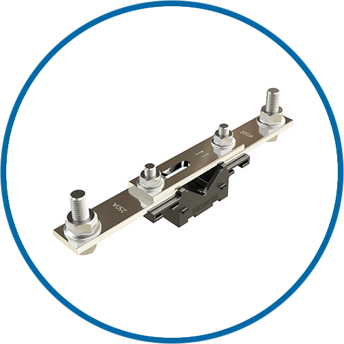
Neutral Links
Covers

Neutral Links
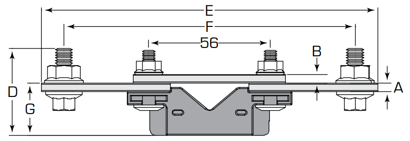
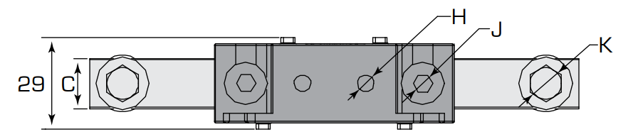
Measurements in mm
| Part Number | 3D Model | Current rating | A | B | C | D | E | F | G(G1) | H | J | K | Box Qty. |
|---|---|---|---|---|---|---|---|---|---|---|---|---|---|
| TNL125 | TNL125 STEP file | 125 A | 4 | 4 | 16 | 40 | 155 | 134 | 24 | 5.5 | M6 | M8×20 | 10 |
| TNL250 | TNL250 STEP file | 250 A | 4 | 4 | 20 | 40 | 165 | 144 | 24 | 5.5 | M6 | M8×20 | 10 |
| TNL400 | TNL400 STEP file | 400 A | 6 | 8 | 30 | 60 | 252 | 228 | 36 (20) | 5.5 | M6 | M10×25 | 5 |
| TNL630 | TNL630 STEP file | 630 A | 8 | 8 | 40 | 60 | 252 | 228 | 36 (20) | 5.5 | M6 | M10×25 | 5 |
| TNL800 | TNL800 STEP file | 800 A | 12 | 12 | 40 | 55 | 273 | 243 | 32 | 5.5 | M6 | M10×40 | 1 |
| TNL1000 | TNL1000 STEP file | 1000 A | 12 | 12 | 50 | 60 | 273 | 243 | 32 | 5.5 | M6 | M10×40 | 1 |
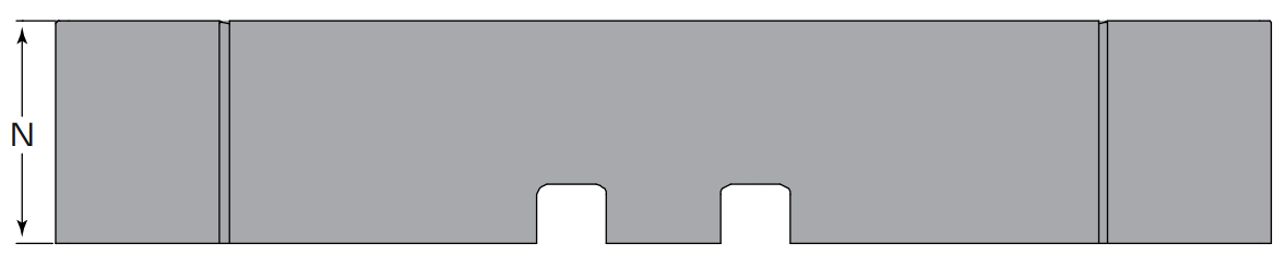
neutral link cover
Measurements in mm
| Part Number | 3D Model | L | M | N | P | Fits Product | Box Qty. |
|---|---|---|---|---|---|---|---|
| TNL250CV | TNL250CV STEP file | 245 | 30 | 45 | 35 | TNL125 & TNL250 | 10 |
| TNL630CV | TNL630CV STEP file | 440 | 45 | 70 | 85 | TNL400 & TNL630 | 5 |
| TNL1000CV | TNL1000CV STEP file | 440 | 60 | 70 | 80 | TNL800 & TNL1000 | 1 |
Technical Specification—Neutral Link
Technical Specification—cover
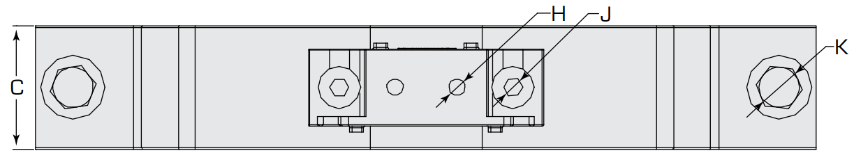
Bottom View: TNL125, TNL250 (Max. Tight Torque M6 6 N·m, M8 19 N·m, (H) 4 N·m)
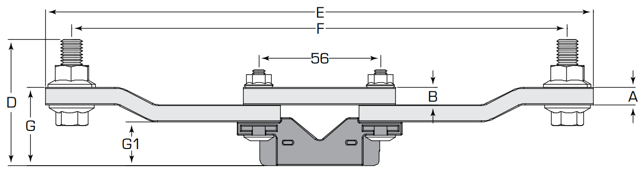
Side View: TNL125, TNL250
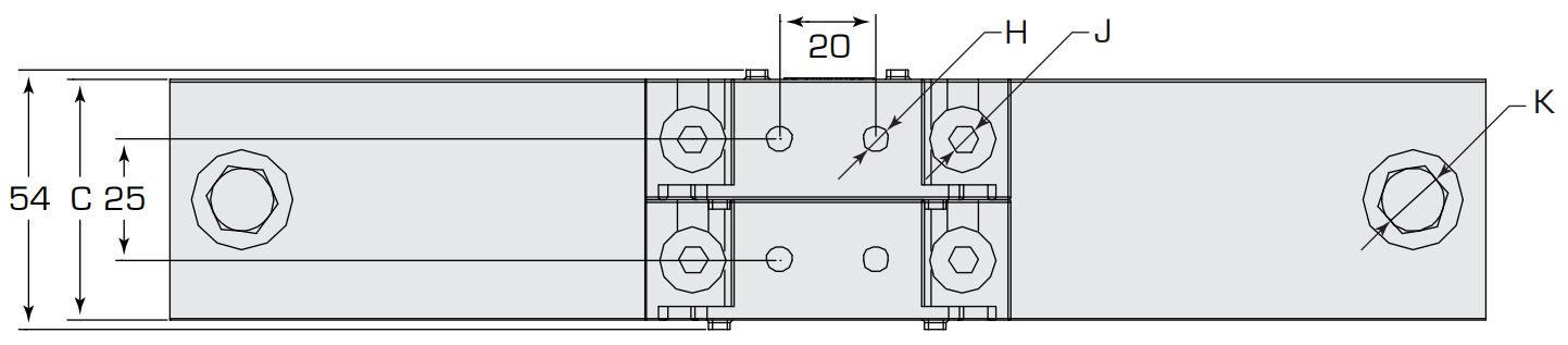
Bottom View: TNL400, TNL630 (Max. Tight Torque M6 6 N·m, M10 32 N·m, (H) 4 N·m)
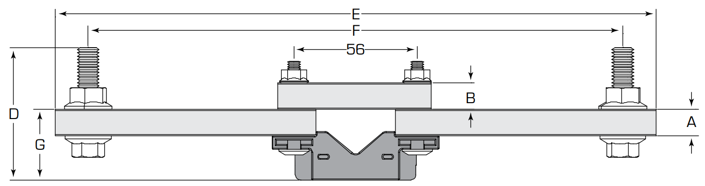
Side View: TNL400, TNL630
Side View: TNL800, TNL1000
Termate is committed to the highest standard of customer focus and we have made every effort to maintain the accuracy and completeness of the information provided in this data. Where improvements to our products affect their installation and usage we endeavour to contact any customers who may be affected.
Warranty as stated in our Terms and Conditions of Trading is void if any modification is made to the warranted product.
Termate’s IEC 61439-2 compliant solution is suitable for arrangements where a 3-pole device is to be fitted but the electrical system requires a neutral link. This reliable and functional solution incorporates an isolation facility and all sizes can be fitted with an optional cover.
Our Neutral Links offers the flexibility of installation as a stand-alone product, providing users with the freedom to choose which method best suits their switchgear requirements.
The combination of IEC 61439-2 conformity, along with this versatility in fitting options, makes Termate’s neutral link ideal for many applications and environments.
With its robust construction and proven reliability, you can trust that it will provide a safe and secure connection every time.
Contact us to receive quick turnaround pricing, delivery lead times or technical assistance.
Termate Limited, John Street, New Basford, Nottingham NG7 7HL, UK
Built By Rise By Digital
Registered in England: 02160675.
Termate Limited © Copyright 2024