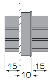
Termate’s range of internal busbar bushings are designed to allow conductors to pass through internal enclosure walls without need for additional insulation.
They enable functional unit separation of Form 2, Form 3 or Form 4 enclosure separation in compliance with IEC 61439-2.
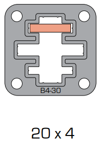
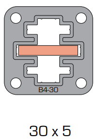
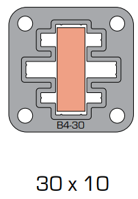
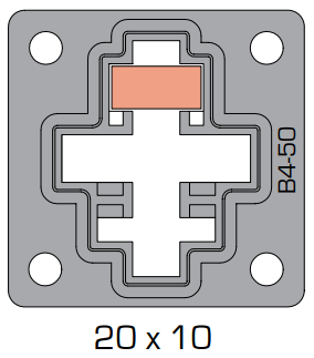
Both designs accept up to four different conductor sizes, from 3 mm up to 10 mm thick.
Compatible insulated cable boots are available for both bushing sizes, these are suitable for Form 4 Type 5 applications (BS EN IEC 61439-2).
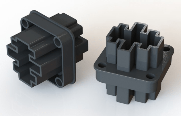

| Part Number | 3D Model | Conductor sizes (mm) | Ue (AC/DC) | Ui (AC/DC) | Uimp |
|---|---|---|---|---|---|
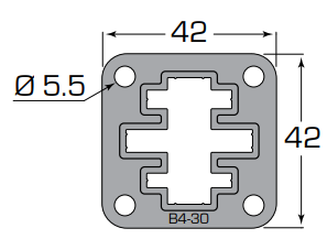
| B4-30 | B4-30 STEP file | 20×3, 20×4, 30×5, 30×10 | 690 V | 690 V | 8 kV |
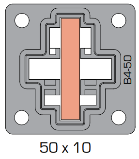
| B4-50 | B4-50 STEP file | 25×5, 20×10, 40×10, 50×10 | 500 V | 500 V | 8 kV |
† In line with the limits set out in IEC 61439, insulating components in contact with conductors may be required to continuously operate at an average of 140 °C (max. 145 °C).
This range of products meets the requirement, the material for them being assigned thermal class F established using methods similar to IEC 60085
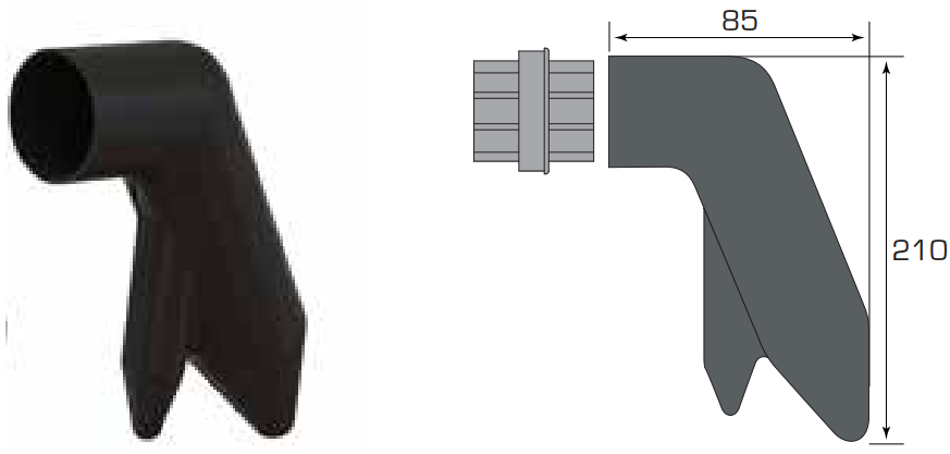


| Part Number | 3D Model | Description | Max. Cable size (mm²) |
|---|---|---|---|
| B4-30BOOT | B4-30BOOT STEP file | Angled Boot for B4-30 | 1×300 2×240 |
| B4-30S-BOOT | B4-30S-BOOT STEP file | Straight Boot for B4-30 | 1×300 |
| B4-50BOOT | B4-50BOOT STEP file | Angled Boot for B4-50 | 1×500 2×300 |







Termate is committed to the highest standard of customer focus and we have made every effort to maintain the accuracy and completeness of the information provided in this data. Where improvements to our products affect their installation and usage we endeavour to contact any customers who may be affected.
Warranty as stated in our Terms and Conditions of Trading is void if any modification is made to the warranted product.