Discontinued DMC Range
The below list has been provided to enable historical reference of our previous range of DMC Supports. Each support has a replacement part shown, along with a link to the replacement part.
For our current DMC range please click HERE
The following supports were discontinued at the end of 2023
All of the supports have a replacement option stated in the right hand column. By following the link you will be guided to the replacement.

3 Phase
6.3 mm or 10 mm Conductor
60–130 mm Phase Centre
- Material: Glass Reinforced Polyester DMC
- Conductor Temp.: 140 °C†
- Flammability: UL 94 V-0
- Glow Wire: 960 °C
- Equipment Voltage, Ue: 1000V AC, 1500 V DC
- Insulation Voltage, Ui: 1000V AC, 1500 V DC
- Impulse Voltage, Uimp: 12 kV
- UL Recognised Component: File number E505645
† In line with the requirements set out in IEC 61439 the supports are capable of carrying conductors operating at an average of 140 °C (max. 145 °C), the material for the supports having a satisfactory thermal index value established using methods similar to IEC 60216.
Reference
| Part Number | Number of Phases | Conductor Width (mm) | Phase Centres | Bars Per Phase | Termate Icw Rating | Replacement Part |
|---|---|---|---|---|---|---|
| 3603BS | 3 | 6.3 | 60 | 1 | 50 kA 1 s | MXM6013NS‡ |
| 3653BS | 3 | 6.3 | 65 | 1 | 50 kA 1 s | MXM6513NS‡ |
| 3603MS | 3 | 10 | 60 | 1 | 50 kA 1 s | MXM6013NS |
| 3653MS | 3 | 10 | 65 | 1 | 50 kA 1 s | MXM6513NS |
| 31303P1 | 3 | 10 | 130 | 1 | 100 kA 1 s | VMS Range‡ |
| 31303P2 | 3 | 10 | 130 | 2 | 100 kA 1 s | VMS Range‡ |
| 31303P3 | 3 | 10 | 130 | 3 | 100 kA 1 s | VMS Range‡ |
‡ Not a direct replacement.
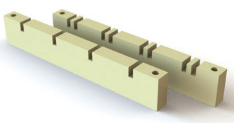
Dimensions
| Part Number | Length (L) | Width (W) | Height (H) | Slot Width (SW) | Base to Bar Height (H1) | Slot Centres (SC) | Fix Centres (FC) | Clearance (C) |
|---|---|---|---|---|---|---|---|---|
| 3603BS | 200 | 20 | 45 | 6.7 | 31.8 | 60 | 178 | 21 |
| 3653BS | 210 | 20 | 45 | 6.7 | 31.8 | 65 | 188 | 21 |
| 3603MS | 200 | 20 | 45 | 10.2 | 31.8 | 60 | 178 | 19 |
| 3653MS | 210 | 20 | 45 | 10.2 | 31.8 | 65 | 188 | 19 |
| 31303P1 | 470 | 20 | 45 | 10.1 | 32 | 130 | 448 | 85 |
| 31303P2 | 470 | 20 | 45 | 30.3 | 32 | 130 | 448 | 75 |
| 31303P3 | 470 | 20 | 45 | 50.5 | 32 | 130 | 448 | 65 |
All dimensions are given in mm.

3 Phase + Neutral
6.3 mm Conductor
65 mm Phase Centre
- Material: Glass Reinforced Polyester DMC
- Conductor Temp.: 140 °C†
- Flammability: UL 94 V-0
- Glow Wire: 960 °C
- Equipment Voltage, Ue: 1000 V AC, 1500 V DC
- Insulation Voltage, Ui: 1000 V AC, 1500 V DC
- Impulse Voltage, Uimp: 12 kV
- UL Recognised Component: File number E505645
† In line with the requirements set out in IEC 61439 the supports are capable of carrying conductors operating at an average of 140 °C (max. 145 °C), the material for the supports having a satisfactory thermal index value established using methods similar to IEC 60216.
Reference
Dimensions
| Part Number | Length (L) | Width (W) | Height (H) | Slot Width (SW) | Base to Bar Height (H1) | Slot Centres (SC) | Fix Centres (FC) | Clearance (C) |
|---|---|---|---|---|---|---|---|---|
| 3604BS | 260 | 20 | 45 | 6.7 | 32 | 60 | 238 | 21 |
| 3654BS | 275 | 20 | 45 | 6.7 | 31.8 | 65 | 253 | 21 |
| 3654TBS | 275 | 20 | 45 | 6.7 | 32 | 65 | 253 | 14 |
All dimensions are given in mm.

3 Phase + Neutral
10 mm Conductor
65–110 mm Phase Centre
- Material: Glass Reinforced Polyester DMC
- Conductor Temp.: 140 °C†
- Flammability: UL 94 V-0
- Glow Wire: 960 °C
- Equipment Voltage, Ue: 1000 V AC, 1500 V DC
- Insulation Voltage, Ui: 1000 V AC, 1500 V DC
- Impulse Voltage, Uimp: 12 kV
- UL Recognised Component: File number E505645
† In line with the requirements set out in IEC 61439 the supports are capable of carrying conductors operating at an average of 140 °C (max. 145 °C), the material for the supports having a satisfactory thermal index value established using methods similar to IEC 60216.
Reference
| Part Number | Number of Phase | Conductor Width (mm) | Phase Centres | Bars Per Phase | Termate Icw Rating | Replacement Part |
|---|---|---|---|---|---|---|
| 3604MS | 4 | 10 | 60 | 1 | 50 kA 1 s | MXM6014NS |
| 3654MS | 4 | 10 | 65 | 1 | 50 kA 1 s | MXM6514NS |
| 30904MS | 4 | 10 | 90 | 1 | 50 kA 1 s | VMS Range‡ |
| 30904DSS | 4 | 10 | 90 | 2 | 50 kA 1 s | VMS Range‡ |
| 31104MS | 4 | 10 | 110 | 1 | 80 kA 1 s | 31104-1 |
| 31104DSS | 4 | 10 | 110 | 2 | 80 kA 1 s | 31104-2 |
| 31104MSS | 4 | 10 | 110 | 3 | 80 kA 1 s | 31104-3 |
| 31104P3 | 4 | 10 | 110 | 3 | 100 kA 1 s* | 31104-3 |
| 31104TMS# | 4 | 10 | 110 | 1, 2 or 3 | 50 kA 3 s | 31104-1 31104-2 31104-3 |
‡ Not a direct replacement.
* Tested as part of Termate Power Plus System.
# Not a recognised UL component.
Dimensions
| Part Number | Length (L) | Width (W) | Height (H) | Slot Width (SW) | Base to Bar Height (H1) | Slot Centres (SC) | Fix Centres (FC) | Clearance (C) |
|---|---|---|---|---|---|---|---|---|
| 3654MS | 275 | 20 | 45 | 10.2 | 31.8 | 65 | 253 | 19 |
| 30904MS | 470 | 20 | 45 | 10.1 | 34.5 | 90 | 448 | 79.5 |
| 30904DSS | 470 | 20 | 45 | 30.3 | 34.5 | 90 | 448 | 70 |
| 31104MS | 470 | 20 | 45 | 10.1 | 34.5 | 110 | 448 | 50.5 |
| 31104DSS | 470 | 20 | 45 | 30.3 | 34.5 | 110 | 448 | 40.5 |
| 31104MSS | 470 | 20 | 45 | 50.5 | 34.9 | 110 | 448 | 30.5 |
| 31104P3 | 470 | 20 | 45 | 50.5 | 32 | 110 | 448 | 30.5 |
| 31104TMS | 470 | 20 (44)* | 45 | 10.1 | 34.7* | 110 | 448 | 30 |
All dimensions are given in mm.
* With inserts fitted.
3 PHASE + NEUTRAL
10 mm Conductor
115–130 mm phase centre
- Material: Glass Reinforced Polyester DMC
- Conductor Temp.: 140 °C†
- Flammability: UL 94 V-0
- Glow Wire: 960 °C
- Equipment Voltage, Ue: 1000 V AC, 1500 V DC
- Insulation Voltage, Ui: 1000 V AC, 1500 V DC
- Impulse Voltage, Uimp: 12 kV
- UL Recognised Component: File number E505645
† In line with the requirements set out in IEC 61439 the supports are capable of carrying conductors operating at an average of 140 °C (max. 145 °C), the material for the supports having a satisfactory thermal index value established using methods similar to IEC 60216.
Reference
| Part Number | Number of Phases | Conductor Width (mm) | Phase Centres | Bars Per Phase | Termate Icw Rating | Replacement Part |
|---|---|---|---|---|---|---|
| 31154M1 | 4 | 10 | 115 | 1 | 100 kA 1 s* | 31154-1 |
| 31154M2 | 4 | 10 | 115 | 2 | 100 kA 1 s* | 31154-D |
| 31154M3 | 4 | 10 | 115 | 3 | 100 kA 1 s* | 31154-T |
| 31304P1 | 4 | 10 | 130 | 1 | 100 kA 1 s* | 31304-1 |
| 31304P2 | 4 | 10 | 130 | 2 | 100 kA 1 s* | 31304-2 |
| 31304P3 | 4 | 10 | 130 | 3 | 100 kA 1 s* | 31304-3 |
| 31304TMS# | 4 | 10 | 130 | 3 | 80 kA 1 s | 31304-3 |
‡ Not a direct replacement.
* Tested as part of Termate Power Plus System.
# Not a recognised UL component.
Dimensions
| Part Number | Length (L) | Width (W) | Height (H) | Slot Width (SW) | Base to Bar Height (H1) | Slot Centres (SC) | Fix Centres (FC) | Clearance (C) |
|---|---|---|---|---|---|---|---|---|
| 31154M1 | 582 | 20 | 45 | 10.1 | 34.5 | 115 | 560 | 98.5 |
| 31154M2 | 582 | 20 | 45 | 20.3 | 34.5 | 115 | 560 | 94.5 |
| 31154M3 | 582 | 20 | 45 | 30.3 | 34.5 | 115 | 560 | 88.5 |
| 31304P1 | 582 | 20 | 45 | 10.1 | 32 | 130 | 560 | 75 |
| 31304P2 | 582 | 20 | 45 | 30.3 | 32 | 130 | 560 | 65 |
| 31304P3 | 582 | 20 | 45 | 50.5 | 32 | 130 | 560 | 55 |
| 31304TMS | 582 | 20 (44)* | 45 | 10.2 | 34.7* | 130 | 560 | 35 |
All dimensions are given in mm.
* With inserts fitted.

3 PHASE + NEUTRAL
25 mm flat bar
53 mm phase centre
- Material: Glass Reinforced Polyester DMC
- Conductor Temp.: 140 °C†
- Flammability: UL 94 V-0
- Glow Wire: 960 °C
- Equipment Voltage, Ue: 1000 V AC, 1500 V DC
- Insulation Voltage, Ui: 1000 V AC, 1500 V DC
- Impulse Voltage, Uimp: 12 kV
† In line with the requirements set out in IEC 61439 the supports are capable of carrying conductors operating at an average of 140 °C (max. 145 °C), the material for the supports having a satisfactory thermal index value established using methods similar to IEC 60216.
Reference
| Part Number | Number of Phases | Conductor Size (mm) | [PC] Phase Centres | Bars Per Phase | Termate Icw Rating | Replacement Part |
|---|---|---|---|---|---|---|
| 3534FB | 4 | Flat 25.4×6.3 | 53 | 1 | 20 kA 1 s | Discontinued |
Dimensions
| Part Number | Length (L) | Width (W) | Height (H) | Slot Width (SW) | Base to Bar Height (H1) | Slot Centres (SC) | Fix Centres (FC) | Clearance (C) |
|---|---|---|---|---|---|---|---|---|
| 3534FB | 275 | 20 | 35 | 26 | 31.8 | 53 | 253 | 31.8 |
All dimensions are given in mm.

Spacer Selection Per Assembly
- Material: Polyamide 6
- Operating Temp.: 140 °C
- Flammability: UL 94 V-0
- Glow Wire: 960 °C
Additional spacers required per busbar support
| Part Number | Conductor 38.1 mm | Conductor 50/50.8 mm | Conductor 60 mm | Conductor 63.5 mm | Conductor 75/76.2 mm | Conductor 80 mm | Conductor 100/101.6 mm | Conductor 152.4 mm |
|---|---|---|---|---|---|---|---|---|
| 3603MS | 1 × CP12 | 1 × CP25 | 1 × CP25 2 × MXS5 | 1 × CP25 1 × CP12 | 1 × CP50 | 1 × CP50 2 × MXS5 | 1 × CP50 1 × CP25 | 2 × CP50 1 × CP25 |
| 3653MS | 1 × CP12 | 1 × CP25 | 1 × CP25 2 × MXS5 | 1 × CP25 1 × CP12 | 1 × CP50 | 1 × CP50 2 × MXS5 | 1 × CP50 1 × CP25 | 2 × CP50 1 × CP25 |
| 3653BS | 1 × CP12 | 1 × CP25 | 1 × CP25 2 × MXS5 | 1 × CP25 1 × CP12 | 1 × CP50 | 1 × CP50 2 × MXS5 | 1 × CP50 1 × CP25 | 2 × CP50 1 × CP25 |
| 3654BS | 1 × CP12 | 1 × CP25 | 1 × CP25 2 × MXS5 | 1 × CP25 1 × CP12 | 1 × CP50 | 1 × CP50 2 × MXS5 | 1 × CP50 1 × CP25 | 2 × CP50 1 × CP25 |
| 3603BS | 1 × CP12 | 1 × CP25 | 1 × CP25 2 × MXS5 | 1 × CP25 1 × CP12 | 1 × CP50 | 1 × CP50 2 × MXS5 | 1 × CP50 1 × CP25 | 2 × CP50 1 × CP25 |
| 3654TBS | 1 × CP12 | 1 × CP25 | 1 × CP25 2 × MXS5 | 1 × CP25 1 × CP12 | 1 × CP50 | 1 × CP50 2 × MXS5 | 1 × CP50 1 × CP25 | 2 x CP50 1 x CP25 |
| 3654MS | 1 × CP12 | 1 × CP25 | 1 × CP25 2 × MXS5 | 1 × CP25 1 × CP12 | 1 × CP50 | 1 × CP50 2 × MXS5 | 1 × CP50 1 × CP25 | 2 × CP50 1 × CP25 |
| 31303P1 | 1 × CP12 | 1 × CP25 | 1 × CP25 2 × MXS5 | 1 × CP25 1 × CP12 | 1 × CP50 | 1 × CP50 2 × MXS5 | 1 × CP50 1 × CP25 | 2 × CP50 1 × CP25 |
| 31303P2 | 1 × CP12 | 1 × CP25 | 1 × CP25 2 × MXS5 | 1 × CP25 1 × CP12 | 1 × CP50 | 1 × CP50 2 × MXS5 | 1 × CP50 1 × CP25 | 2 × CP50 1 × CP25 |
| 31303P3 | 1 × CP12 | 1 × CP25 | 1 × CP25 2 × MXS5 | 1 × CP25 1 × CP12 | 1 × CP50 | 1 × CP50 2 × MXS5 | 1 × CP50 1 × CP25 | 2 × CP50 1 × CP25 |
| 31304P1 | 1 × CP12 | 1 × CP25 | 1 × CP25 2 × MXS5 | 1 × CP25 1 × CP12 | 1 × CP50 | 1 × CP50 2 × MXS5 | 1 × CP50 1 × CP25 | 2 × CP50 1 × CP25 |
| 31304P2 | 1 × CP12 | 1 × CP25 | 1 × CP25 2 × MXS5 | 1 × CP25 1 × CP12 | 1 × CP50 | 1 × CP50 2 × MXS5 | 1 × CP50 1 × CP25 | 2 × CP50 1 × CP25 |
| 31304P3 | 1 × CP12 | 1 × CP25 | 1 × CP25 2 × MXS5 | 1 × CP25 1 × CP12 | 1 × CP50 | 1 × CP50 2 × MXS5 | 1 × CP50 1 × CP25 | 2 × CP50 1 × CP25 |
| 31104P3 | 1 × CP12 | 1 × CP25 | 1 × CP25 2 × MXS5 | 1 × CP25 1 × CP12 | 1 × CP50 | 1 × CP50 2 × MXS5 | 1 × CP50 1 × CP25 | 2 × CP50 1 × CP25 |
| 30904DSS | 1 × CP25 1 × MXS5 | 1 × CP25 1 × CP15 | 1 × CP25 1 × CP12 1 × MXS5 | 1 × CP50 1 × MXS5 | 1 × CP50 2 × MXS5 | 1 × CP50 1 × CP25 1 × MXS5 | 2 × CP50 1 × CP25 1 × MXS5 |
|
| 30904MS | 1 × CP25 1 × MXS5 | 1 × CP25 1 × CP15 | 1 × CP25 1 × CP12 1 × MXS5 | 1 × CP50 1 × MXS5 | 1 × CP50 2 × MXS5 | 1 × CP50 1 × CP25 1 × MXS5 | 2 × CP50 1 × CP25 1 × MXS5 |
|
| 31104DSS | 1 × CP25 1 × MXS5 | 1 × CP25 1 × CP15 | 1 × CP25 1 × CP12 1 × MXS5 | 1 × CP50 1 × MXS5 | 1 × CP50 2 × MXS5 | 1 × CP50 1 × CP25 1 × MXS5 | 2 × CP50 1 × CP25 1 × MXS5 |
|
| 31104MS | 1 × CP25 1 × MXS5 | 1 × CP25 1 × CP15 | 1 × CP25 1 × CP12 1 × MXS5 | 1 × CP50 1 × MXS5 | 1 × CP50 2 × MXS5 | 1 × CP50 1 × CP25 1 × MXS5 | 2 × CP50 1 × CP25 1 × MXS5 |
|
| 31154M1 | 1 × CP25 1 × MXS5 | 1 × CP25 1 × CP15 | 1 × CP25 1 × CP12 1 × MXS5 | 1 × CP50 1 × MXS5 | 1 × CP50 2 × MXS5 | 1 × CP50 1 × CP25 1 × MXS5 | 2 × CP50 1 × CP25 1 × MXS5 |
|
| 31154M2 | 1 × CP25 1 × MXS5 | 1 × CP25 1 × CP15 | 1 × CP25 1 × CP12 1 × MXS5 | 1 × CP50 1 × MXS5 | 1 × CP50 2 × MXS5 | 1 × CP50 1 × CP25 1 × MXS5 | 2 × CP50 1 × CP25 1 × MXS5 |
|
| 31154M3 | 1 × CP25 1 × MXS5 | 1 × CP25 1 × CP15 | 1 × CP25 1 × CP12 1 × MXS5 | 1 × CP50 1 × MXS5 | 1 × CP50 2 × MXS5 | 1 × CP50 1 × CP25 1 × MXS5 | 2 × CP50 1 × CP25 1 × MXS5 |
|
| 31304TMS | 1 × CP25 1 × MXS5 | 1 × CP25 1 × CP15 | 1 × CP25 1 × CP12 1 × MXS5 | 1 × CP50 1 × MXS5 | 1 × CP50 2 × MXS5 | 1 × CP50 1 × CP25 1 × MXS5 | 2 × CP50 1 × CP25 1 × MXS5 |
|
| 31104TMS | 1 × CP25 1 × MXS5 | 1 × CP25 1 × CP15 | 1 × CP25 1 × CP12 1 × MXS5 | 1 × CP50 1 × MXS5 | 1 × CP50 2 × MXS5 | 1 × CP50 1 × CP25 1 × MXS5 | 2 × CP50 1 × CP25 1 × MXS5 |
|
| 31104MSS | 1 × CP25 1 × MXS5 | 1 × CP25 1 × CP15 | 1 × CP25 1 × CP12 1 × MXS5 | 1 × CP50 1 × MXS5 | 1 × CP50 2 × MXS5 | 1 × CP50 1 × CP25 1 × MXS5 | 2 × CP50 1 × CP25 1 × MXS5 |
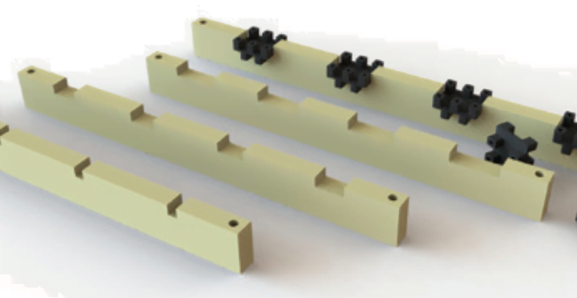
Typical spacer installations
4 Phase, 2 Bar


M8 fixings, recommended tightening torque 10 N·m.
Note: For twin bar per pole systems, in order to retain the appropriate rating, it is essential for the conductors to be kept apart. Whilst fishplates and take-off connections help in this aspect, additional packing pieces must be installed at no more than 500 mm centres.

