

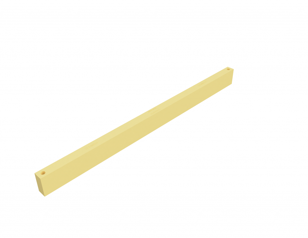

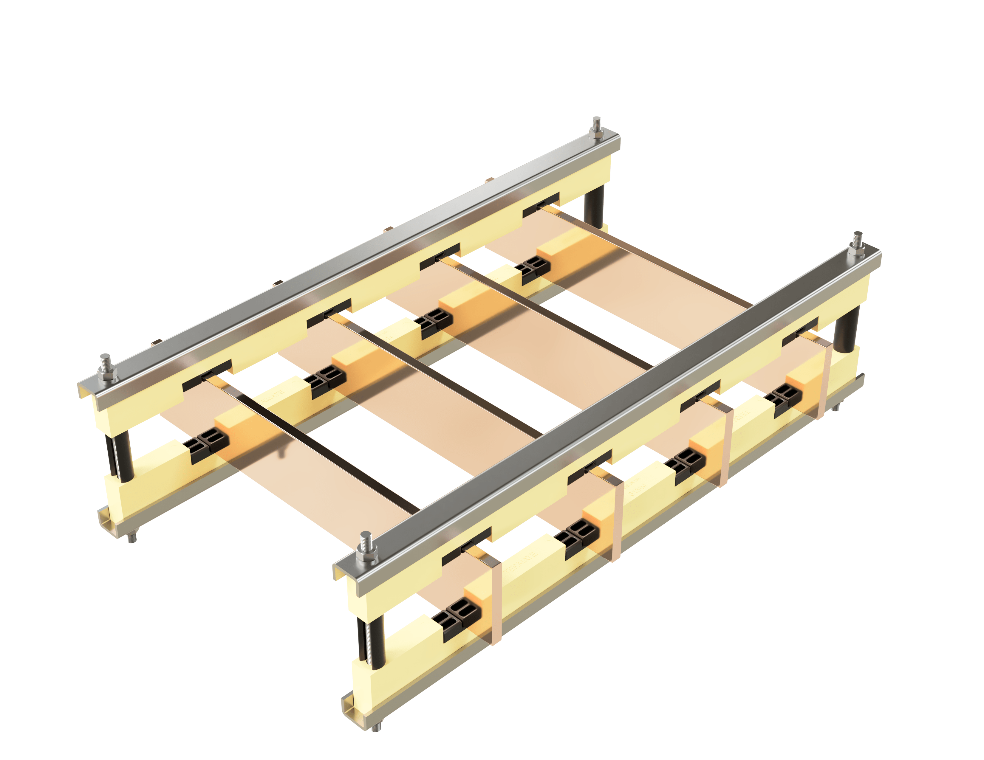


The DMC range encompasses Termate’s traditional busbar supports.
DMC supports are available for Icw ratings up to 100 kA/1 s. These supports are compression moulded, unlike the black busbar supports which are injection moulded. There are a range of supports for different line centres and number of conductors.
† In line with the requirements set out in IEC 61439 the supports are capable of carrying conductors operating at an average of 140 °C (max. 145 °C), the material for the supports having a satisfactory thermal index value established using methods similar to IEC 60216.
Selection
For increased stock flexibility, the following range of supports are available in 2 separate parts, the Body and Insert. These parts are purchased separately and all inserts are interchangeable with all Body supports.
Please review the reference section below for your choice of support. For your ease of design. the associated .STEP file shows the combination of the Inserts and Body.
Reference
| Part Number | 3D Model | Body Part Number | Number required per assembly | Insert Part Number | Number required per assembly | Conductor Width (mm) | Bars per Phase | Phase Centres | Termate Icw Rating | Body Box Qty |
|---|---|---|---|---|---|---|---|---|---|---|
| 31104-1 | 31104-1 STEP file | 31104 | 2 | PM1-10 | 8 | 10 | 1 | 110 | 80 kA 1 s | 20 |
| 31104-2 | 31104-2 STEP file | 31104 | 2 | PM2-10 | 8 | 10 | 2 | 110 | 80 kA 1 s | 20 |
| 31104-3 | 31104-3 STEP file | 31104 | 2 | PM3-10 | 8 | 10 | 3 | 110 | 80 kA 1 s | 20 |
| 31154-1 | 31154-1 STEP file | 31154 | 2 | PM1-10 | 8 | 10 | 1 | 115 | 80 kA 1 s | 20 |
| 31154-2 | 31154-2 STEP file | 31154 | 2 | PM2-10 | 8 | 10 | 2 | 115 | 80 kA 1 s | 20 |
| 31154-3 | 31154-3 STEP file | 31154 | 2 | PM3-10 | 8 | 10 | 3 | 115 | 80 kA 1 s | 20 |
| 31154-D | 31154-D STEP file | 31154 | 2 | PMD-10 | 8 | 10 | 2 - Double sandwiched (NO GAP) | 115 | 80 kA 1 s | 20 |
| 31154-T | 31154-T STEP file | 31154 | 2 | PMT-10 | 8 | 10 | 3 - Triple sandwiched (NO GAP) | 115 | 80 kA 1 s | 20 |
| 31304-1 | 31304-1 STEP file | 31304 | 2 | PM1-10 | 8 | 10 | 1 | 130 | 100 kA 1 s | 20 |
| 31304-2 | 31304-2 STEP file | 31304 | 2 | PM2-10 | 8 | 10 | 2 | 130 | 100 kA 1 s | 20 |
| 31304-3 | 31304-3 STEP file | 31304 | 2 | PM3-10 | 8 | 10 | 3 | 130 | 100 kA 1 s | 20 |
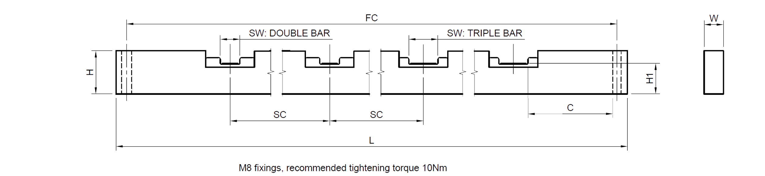
dimensions
| Part Number | Length (L) | Width (W) | Height (H) | Slot Width (SW) | Base to Bar Height (H1) | Slot Centres (SC) | Fix Centres (FC) | Clearance (C) |
|---|---|---|---|---|---|---|---|---|
| 31104-1 | 470 | 20 | 45 | 10.3 | 32 | 110 | 448 | 49 |
| 31104-2 | 470 | 20 | 45 | 10.3 | 32 | 110 | 448 | 39 |
| 31104-3 | 470 | 20 | 45 | 10.3 | 32 | 110 | 448 | 29 |
| 31154-1 | 582 | 20 | 45 | 10.3 | 32 | 115 | 560 | 97 |
| 31154-2 | 582 | 20 | 45 | 10.3 | 32 | 115 | 560 | 87 |
| 31154-3 | 582 | 20 | 45 | 10.3 | 32 | 115 | 560 | 77 |
| 31154-D | 582 | 20 | 45 | 20.3 | 32 | 115 | 560 | 92 |
| 31154-T | 582 | 20 | 45 | 30.3 | 32 | 115 | 560 | 87 |
| 31304-1 | 582 | 20 | 45 | 10.3 | 32 | 130 | 560 | 75 |
| 31304-2 | 582 | 20 | 45 | 10.3 | 32 | 130 | 560 | 65 |
| 31304-3 | 582 | 20 | 45 | 10.3 | 32 | 130 | 560 | 55 |
All dimensions are given in mm.
† In line with the requirements set out in IEC 61439 the supports are capable of carrying conductors operating at an average of 140 °C (max. 145 °C), the material for the supports having a satisfactory thermal index value established using methods similar to IEC 60216.
Reference
| Part Number | 3D Model | Number of Poles | Conductor Width mm | Phase Centres | Bars Per Pole | Termate Icw Rating | Box Qty |
|---|---|---|---|---|---|---|---|
| 3470BBS | 3470BBS STEP file | - | - | Blank | - | - | 20 |
| 3582BBS | 3582BBS STEP file | - | - | Blank | - | - | 20 |
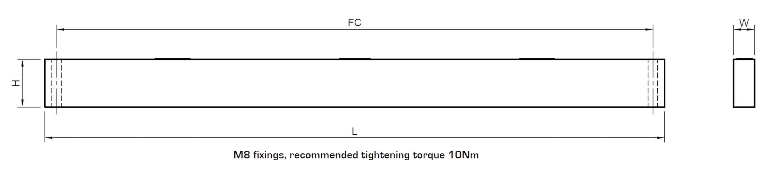
Dimensions
| Part Number | Length (L) | Width (W) | Height (H) | Slot Width (SW) | Base to Bar Height (H1) | Slot Centres (SC) | Fix Centres (FC) | Clearance (C) |
|---|---|---|---|---|---|---|---|---|
| 3470BBS | 470 | 20 | 45 | - | - | - | 448 | - |
| 3582BBS | 582 | 20 | 45 | - | - | - | 560 | - |
All dimensions are given in mm.
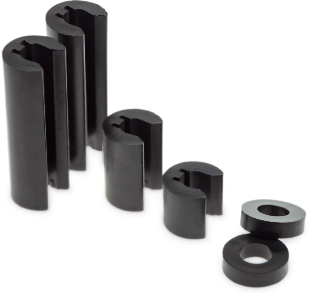
Additional Spacers Required Per Busbar Support
| Part Number | Conductor 40 mm | Conductor 50 mm | Conductor 60 mm | Conductor 75 mm | Conductor 80 mm | Conductor 100 mm | Conductor 150 mm |
|---|---|---|---|---|---|---|---|
| 31104-1 31104-2 31104-3 | 1 × CP15 | 1 × CP25 | 1 × CP25 2 × MXS5 | 1 × CP50 | 1 × CP50 1 × MXS5 | 1 × CP50 1 × CP25 | 2 × CP50 1 × CP25 |
| 31154-1 31154-2 31154-3 | 1 × CP15 | 1 × CP25 | 1 × CP25 2 × MXS5 | 1 × CP50 | 1 × CP50 1 × MXS5 | 1 × CP50 1 × CP25 | 2 × CP50 1 × CP25 |
| 31304-1 31304-2 31304-3 | 1 × CP15 | 1 × CP25 | 1 × CP25 2 × MXS5 | 1 × CP50 | 1 × CP50 1 × MXS5 | 1 × CP50 1 × CP25 | 2 × CP50 1 × CP25 |
Typical Spacer Installations
4 Phase 1 Bar
† In line with the requirements set out in IEC 61439 the supports are capable of carrying conductors operating at an average of 140 °C (max. 145 °C), the material for the supports having a satisfactory thermal index value established using methods similar to IEC 60216.
| Part Number | Number of Phases | Conductor Width (mm) | Phase Centres | Bars Per Phase | Termate Icw Rating |
|---|---|---|---|---|---|
| 360D-19 | 4 | 6.3 | 60 | 2 | 31 kA 1 s |
| 360D-25 | 4 | 6.3 | 60 | 2 | 31 kA 1 s |
Please note: The 360D-19 & 360D-25 use the same body (360D). The 360D-19 is designed for 19.05 mm and the 360D-25 is designed for 25.4mm conductors.
| Part Number | Length (L) | Width (W) | Height (H) | Slot Width (SW) | Base to Bar Height (H1) | Slot Centres (SC) | Fix Centres (FC) | Clearance (C) |
|---|---|---|---|---|---|---|---|---|
| 360D | 275 | 20 | 55 | 6.5 | 43.5 | 60 | 253 | 19 |
All dimensions are given in mm.
Termate is committed to the highest standard of customer focus and we have made every effort to maintain the accuracy and completeness of the information provided in this data. Where improvements to our products affect their installation and usage we endeavour to contact any customers who may be affected.
Warranty as stated in our Terms and Conditions of Trading is void if any modification is made to the warranted product.
Please contact us to receive a quote, application help or learn more about any of our products
Termate Limited, John Street, New Basford, Nottingham NG7 7HL, UK
Built By Rise By Digital
Registered in England: 02160675.
Termate Limited © Copyright 2024

