VMS Range
The VMS range offers a versatile solution with a superb Icw rating. As a single phase support, they can be installed to suit your application. Whether AC or DC.
The VMS range of supports achieve fault ratings of up to Icw rating of 100 kA/1 s.
Each support can hold one, two or three conductors, and can be used without spacers to give any desired conductor centres or with spacers to create 110 mm, 122.5 mm and 130 mm conductor centres.
- Up to 100 kA/1 s fault rating
- Single phase units to give a wide scope for design and application
- UL Recognised Component; File Number: E505645

VMS Busbar Supports & Spacers
VMS3-10, VMS-S110, VMS-S122.5 & VMS-S130
† In line with the limits set out in IEC 61439, insulating components in contact with conductors may be required to continuously operate at an average of 140 °C (max. 145 °C).
This range of products meets the requirement, the material for them being assigned thermal class F established using methods similar to IEC 60085.
Fault Levels—Insulator tested at 300 mm spacing
| Part Number | 3D Model | Conductors | Support Phase Centres | Termate Icw Rating | Duration | Spacer Part Number | Spacer 3D Model | Spacer Requirement |
|---|---|---|---|---|---|---|---|---|
| VMS3-10 | VMS3-10 STEP file | 2 × 100×10 | 110 | 65 kA | 3 s | VMS-S110 | VMS-S110 STEP file | Optional |
| VMS3-10 | VMS3-10 STEP file | 2 × 100×10 | 110 | 80 kA | 1 s | VMS-S110 | VMS-S110 STEP file | Optional |
| VMS3-10 | VMS3-10 STEP file | 2 × 100×10 | 122.5 | 80 kA*# | 1 s | VMS-S122.5 | VMS-S122.5 STEP file | Optional |
| VMS3-10 | VMS3-10 STEP file | 2 × 100×10 | 130 | 65 kA | 3 s | VMS-S130 | VMS-S130 STEP file | Optional |
| VMS3-10 | VMS3-10 STEP file | 2 × 100×10 | 130 | 80 kA | 1 s | VMS-S130 | VMS-S130 STEP file | Optional |
| VMS3-10 | VMS3-10 STEP file | 2 × 100×10 | 130 | 100 kA | 1 s | VMS-S130 | VMS-S130 STEP file | Required |
* Fault level extrapolated from data achieved for the VMS-S110
# Part not included in UL Recognised Component File
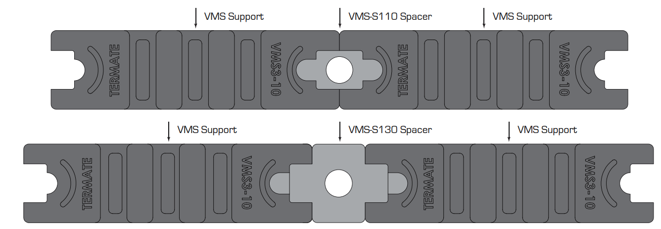
Plan view of VMS Support and Spacers

VMS3-10 Busbar Support

VMS-S110 Spacer

VMS-S130 Spacer

Typical Installations
3 pole assembly at 130 mm phase centres using spacers

4 pole assembly at 110 mm phase centres using spacers

3 pole assembly—versatile mounting

Typical assembly

Termate is committed to the highest standard of customer focus and we have made every effort to maintain the accuracy and completeness of the information provided in this data. Where improvements to our products affect their installation and usage we endeavour to contact any customers who may be affected.
Warranty as stated in our Terms and Conditions of Trading is void if any modification is made to the warranted product.


