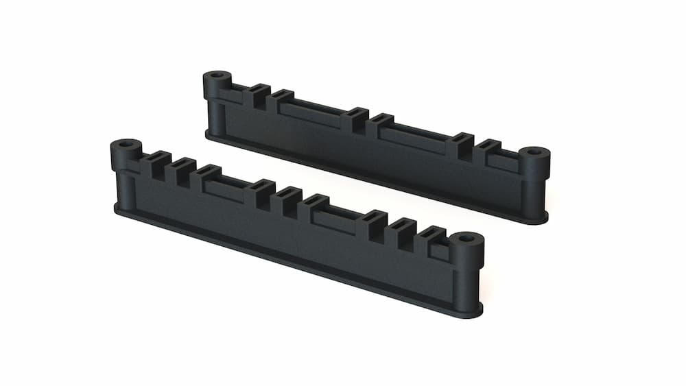
MX Range
The MX range of busbar supports are available in a variety of fixed configurations, offering supports for your entire range of panels with the same uniform and sleek design.
The MX range offers Icw ratings of up to 65 kA/3 s.
These multi-phase supports offer quick and easy installation for three phase or three phase and neutral requirements. Versions are available for different conductor centres, number of phases and bars.
Supports are also available to fit insulated copper, with both metric and imperial versions.
- Up to 65 kA/3 s fault rating
- UL Recognised Component; File Number: E505645
3 Phase
10 mm Conductor
60–110 mm PHASE CENTRE
† In line with the limits set out in IEC 61439, insulating components in contact with conductors may be required to continuously operate at an average of 140 °C (max. 145 °C).
This range of products meets the requirement, the material for them being assigned thermal class F established using methods similar to IEC 60085.
Reference
| Part Number | 3D Model | Number of Phases | Conductor Width (mm) | Phase Centres | Bars Per Phase | Termate Icw Rating |
|---|---|---|---|---|---|---|
| MXM6013NS | MXM6013NS STEP file | 3 | 10 | 60 | 1 | 50 kA 1 s |
| MXM6513NS | MXM6513NS STEP file | 3 | 10 | 65 | 1 | 50 kA 1 s |
| MXM8213NS | MXM8213NS STEP file | 3 | 10 | 82 | 1 | 65 kA 3 s |
| MXM8223NS | MXM8223NS STEP file | 3 | 10 | 82 | 2 | 65 kA 3 s |
| MXM11013NS | MXM11013NS STEP file | 3 | 10 | 110 | 1 | 65 kA 3 s |
| MXM11023NS | MXM11023NS STEP file | 3 | 10 | 110 | 2 | 65 kA 3 s |
Termate Icw rating tested with supports at 300 mm centres
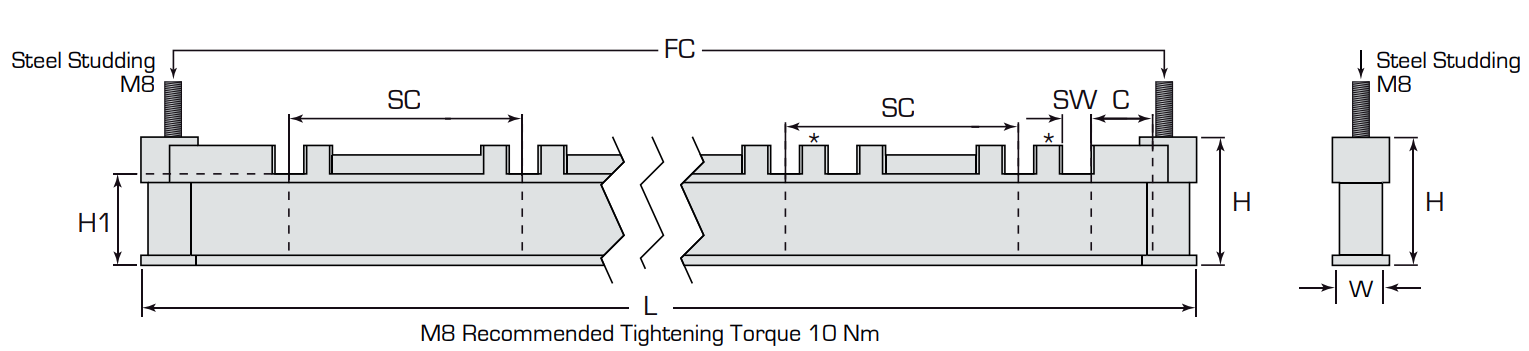
Dimensions
| Part Number | Length (L) | Width (W) | Height (H) | Slot Width (SW) | Base to Bar Height (H1) | Slot Centres (SC) | Fix Centres (FC) | Clearance (C) |
|---|---|---|---|---|---|---|---|---|
| MXM6013NS | 210 | 20 | 44.7 | 10.2 | 32 | 60 | 190 | 25.4 |
| MXM6513NS | 210 | 20 | 44.7 | 10.2 | 32 | 65 | 190 | 25.4 |
| MXM8213NS | 273 | 20 | 44.7 | 10.1 | 32 | 82 | 253 | 34.5 |
| MXM8223NS | 273 | 20 | 44.7 | 10.1 | 32 | 82 | 253 | 24.5 |
| MXM11013NS | 350 | 20 | 44.7 | 10.1 | 32 | 110 | 330 | 45 |
| MXM11023NS | 350 | 20 | 44.7 | 10.1 | 32 | 110 | 330 | 35 |
All dimensions are given in mm
Please refer to the spacer selection table for recommended spacers which must be ordered separately.
If using another method of fixing, please take into account the reduced creepage and clearance distances to the adjacent busbar.
* For the 2 bar version the dimension of the pip between the bars is the same as the slot width

3 Phase + Neutral
6 or 6.3 mm Conductor
60–82 mm PHASE CENTRE
† In line with the limits set out in IEC 61439, insulating components in contact with conductors may be required to continuously operate at an average of 140 °C (max. 145 °C).
This range of products meets the requirement, the material for them being assigned thermal class F established using methods similar to IEC 60085.
Reference
| Part Number | 3D Model | Number of Phases | Conductor Width (mm) | Phase Centres | Bars Per Phase | Termate Icw Rating |
|---|---|---|---|---|---|---|
| MX68224NS | MX68224NS STEP file | 4 | 6 | 82 | 2 | 65 kA 3 s |
| MXB6014NS | MXB6014NS STEP file | 4 | 6.3 | 60 | 1 | 50 kA 1 s |
| MXB6514NS | MXB6514NS STEP file | 4 | 6.3 | 65 | 1 | 50 kA 1 s |
| MXB6524NS | MXB6524NS STEP file | 4 | 6.3 | 65 | 2 | 65 kA 3 s |
DIMENSIONS
| Part Number | Length (L) | Width (W) | Height (H) | Slot Width (SW) | Base to Bar Height (H1) | Slot Centres (SC) | Fix Centres (FC) | Clearance (C) |
|---|---|---|---|---|---|---|---|---|
| MX68224NS | 350 | 20 | 45.5 | 6.1 | 32 | 82 | 330 | 28 |
| MXB6014NS | 273 | 20 | 45.5 | 6.7 | 32 | 60 | 253 | 28.5 |
| MXB6514NS | 273 | 20 | 45.5 | 6.7 | 32 | 65 | 253 | 20.5 |
| MXB6524NS | 273 | 20 | 45.5 | 6.5 | 32 | 65 | 253 | 14 |
All dimensions are given in mm
Please refer to the spacer selection table for recommended spacers which must be ordered separately.
If using another method of fixing, please take into account the reduced creepage and clearance distances to the adjacent busbar.
* For the 2 bar version the dimension of the pip between the bars is the same as the slot width
3 phase + Neutral
10 mm Conductor
60–82 mm PHASE CENTRE
Type 1
- Equipment Voltage, Ue: 1000 V AC, 1500 V DC
- Insulation Voltage, Ui: 1000 V AC, 1500 V DC
- Impulse Voltage, Uimp: 12 kV
Type 2
- Equipment Voltage, Ue: 690 V AC, 690 V DC
- Insulation Voltage, Ui: 690 V AC, 690 V DC
- Impulse Voltage, Uimp: 8 kV
† In line with the limits set out in IEC 61439, insulating components in contact with conductors may be required to continuously operate at an average of 140 °C (max. 145 °C).
This range of products meets the requirement, the material for them being assigned thermal class F established using methods similar to IEC 60085.
Reference
| Part Number | 3D Model | Number of Phases | Conductor Width (mm) | Phase Centres | Bars Per Phase | Termate Icw Rating | Type |
|---|---|---|---|---|---|---|---|
| MXM6014NS | MXM6014NS STEP file | 4 | 10 | 60 | 1 | 50 kA 1 s | 1 |
| MXM6514NS | MXM6514NS STEP file | 4 | 10 | 65 | 1 | 50 kA 3 s | 1 |
| MXM6524NS | MXM6524NS STEP file | 4 | 10 | 65 | 2 | 65 kA 3 s | 2 |
| MXHM7014NS | MXHM7014NS STEP file | 4 | 10 | 70 | 1 | 50 kA 3 s | 1 |
| MXM8214NS | MXM8214NS STEP file | 4 | 10 | 82 | 1 | 65 kA 3 s | 1 |
| MXM8224NS | MXM8224NS STEP file | 4 | 10 | 82 | 2 | 65 kA 3 s | 1 |
Termate Icw rating tested with supports at 300 mm centres
DIMENSIONS
| Part Number | Length (L) | Width (W) | Height (H) | Slot Width (SW) | Base to Bar Height (H1) | Slot Centres (SC) | Fix Centres (FC) | Clearance (C) |
|---|---|---|---|---|---|---|---|---|
| MXM6014NS | 273 | 20 | 44.7 | 10.2 | 32 | 60 | 253 | 26.5 |
| MXM6514NS | 273 | 20 | 44.7 | 10.2 | 32 | 65 | 253 | 19 |
| MXM6524NS | 273 | 20 | 44.7 | 10.2 | 32 | 65 | 253 | 8.5 |
| MXHM7014NS | 350 | 20 | 44.7 | 10.1 | 32 | 70 | 330 | 37.5/62.5 |
| MXM8214NS | 350 | 20 | 44.7 | 10.1 | 32 | 82 | 330 | 32 |
| MXM8224NS | 350 | 20 | 44.7 | 10.1 | 32 | 82 | 330 | 32 |
All dimensions are given in mm
Please refer to the spacer selection table for recommended spacers which must be ordered separately.
If using another method of fixing, please take into account the reduced creepage and clearance distances to the adjacent busbar.
* For the 2 bar version the dimension of the pip between the bars is the same as the slot width

for insulated conductors
3 Phase + Neutral
6–10 mm Conductors
65–82 mm PHASE CENTRE
† In line with the limits set out in IEC 61439, insulating components in contact with conductors may be required to continuously operate at an average of 140 °C (max. 145 °C).
This range of products meets the requirement, the material for them being assigned thermal class F established using methods similar to IEC 60085
Reference
| Part Number | 3D Model | Number of Phases | Conductor Width (mm) | Phase Centres | Bars Per Phase | Termate Icw Rating | Insulated |
|---|---|---|---|---|---|---|---|
| MX6I8224NS | MX6I8224NS STEP file | 4 | 6* | 82 | 2 | 50 kA 1 s | Yes |
| MXI6514NS | MXI6514NS STEP file | 4 | 6* | 65 | 1 | 50 kA 1 s | Yes |
| MXMI8214NS | MXMI8214NS STEP file | 4 | 10* | 82 | 1 | 50 kA 1 s | Yes |
* Conductor width shown is nominal copper width. Total width of conductor including insulation cannot exceed Slot Width (SW) shown below.
DIMENSIONS
| Part Number | Length (L) | Width (W) | Height (H) | Slot Width (SW) | Base to Bar Height (H1) | Slot Centres (SC) | Fix Centres (FC) | Clearance (C) |
|---|---|---|---|---|---|---|---|---|
| MX6I8224NS | 350 | 20 | 45.5 | 7.5 | 32 | 82 | 330 | 27.5 |
| MXI6514NS | 273 | 20 | 45.5 | 7.5 | 32 | 65 | 253 | 20 |
| MXMI8214NS | 350 | 20 | 44.7 | 11 | 32 | 82 | 330 | 32 |
All dimensions are given in mm
Please refer to the spacer selection table for recommended spacers which must be ordered separately.
If using another method of fixing, please take into account the reduced creepage and clearance distances to the adjacent busbar.
*For the 2 bar version, the dimension of the pip between the bars is smaller than the slot width, this allows for the insulation material. The gap between the installed conductors is expected to be the same as the thickness of the conductors.

3 PHASE
Flat 10mm Conductor
70MM PHASE CENTRE
† In line with the limits set out in IEC 61439, insulating components in contact with conductors may be required to continuously operate at an average of 140 °C (max. 145 °C).
This range of products meets the requirement, the material for them being assigned thermal class F established using methods similar to IEC 60085.
Reference
| Part Number | 3D Model | Number of Phases | Conductor Width (mm) | Phase Centres | Bars Per Phase | Termate Icw Rating |
|---|---|---|---|---|---|---|
| MXMF407513NS | MXMF407513NS STEP file | 3 | 40 | 75 | 1 | 50 kA 1 s |
| MXMF507513NS | MXMF507513NS STEP file | 3 | 50 | 75 | 1 | 50 kA 1 s |
DIMENSIONS
| Part Number | Length (L) | Width (W) | Height (H) | Slot Width (SW) | Base to Bar Height (H1) | Slot Centres (SC) | Fix Centres (FC) | Clearance (C) |
|---|---|---|---|---|---|---|---|---|
| MXMF407513NS | 273 | 20 | 37 | 40.5 | 32 | 75 | 253 | 26 |
| MXMF507513NS | 273 | 20 | 37 | 40.5 | 32 | 75 | 253 | 21 |
All dimensions are given in mm

If using another method of fixing, please take into account the reduced creepage and clearance distances to the adjacent busbar.

3 PHASE + NEUTRAL
Flat 10mm Conductor
75MM PHASE CENTRE
† In line with the limits set out in IEC 61439, insulating components in contact with conductors may be required to continuously operate at an average of 140 °C (max. 145 °C).
This range of products meets the requirement, the material for them being assigned thermal class F established using methods similar to IEC 60085.
Reference
| Part Number | 3D Model | Number of Phases | Conductor Width (mm) | Phase Centres | Bars Per Phase | Termate Icw Rating |
|---|---|---|---|---|---|---|
| MXMF407514NS | MXMF407514NS STEP file | 4 | 40 | 75 | 1 | 50 kA 1 s |
| MXMF507514NS | MXMF507514NS STEP file | 4 | 50 | 75 | 1 | 50 kA 1 s |
DIMENSIONS
| Part Number | Length (L) | Width (W) | Height (H) | Slot Width (SW) | Base to Bar Height (H1) | Slot Centres (SC) | Fix Centres (FC) | Clearance (C) |
|---|---|---|---|---|---|---|---|---|
| MXMF407514NS | 350 | 20 | 37 | 40.5 | 32 | 75 | 330 | 27 |
| MXMF507514NS | 350 | 20 | 37 | 50.5 | 32 | 75 | 330 | 22 |
If using another method of fixing, please take into account the reduced creepage and clearance distances to the adjacent busbar.

Spacer Selection Per Assembly
- Material: Polyamide 6
- Conductor Temp.: 140 °C†
- Flammability: UL 94 V-0
- Glow Wire: 960 °C
† In line with the limits set out in IEC 61439, insulating components in contact with conductors may be required to continuously operate at an average of 140 °C (max. 145 °C).
This range of products meets the requirement, the material for them being assigned thermal class F established using methods similar to IEC 60085.
Number of spacers per MX Support
| Conductor 25/25.4 mm | Conductor 30 mm | Conductor 50/50.8 mm | Conductor 60 mm | Conductor 75/76.2 mm | Conductor 80 mm | Conductor 100/101.6 mm |
|---|---|---|---|---|---|---|
| Not Required | 1 × MXS5 | 1 × CP25 | 1 × CP25 + 2 × MXS5 | 1 × CP50 | 1 × CP50 +1 × MXS5 | 1 × CP50 +1 × CP25 |
NOTE: Number of spacer is per support (2 supports requred per support assembly)
If the conductor being supported is greater than 100mm, additional spacers can be added as required using the principle as detailed in the above table. We do not recommend this installation method if the conductor exceeds 200mm high.
MXMF407513NS, MXMF507513NS, MXMF407514NS, and MXMF507514NS supports do not require spacers
Typical Installations


Termate is committed to the highest standard of customer focus and we have made every effort to maintain the accuracy and completeness of the information provided in this data. Where improvements to our products affect their installation and usage we endeavour to contact any customers who may be affected.
Warranty as stated in our Terms and Conditions of Trading is void if any modification is made to the warranted product.

