If you work in electrical engineering design, you know that a busbar support is a critical part of any power system. They should provide mechanical and electrical support to the installed conductors. In addition, should a short circuit event occur, the support should minimise the damage to the system and reduce the potential of a fire.
In this article, we’ll discuss everything you need to know about busbar supports, including their purpose, how they’re made, and what sizes and types are available. We’ll also touch on the benefits of using glass-reinforced polyamide in their construction and some of the industry specifications that cover their use. Finally, we’ll provide an overview of where busbar supports are manufactured.

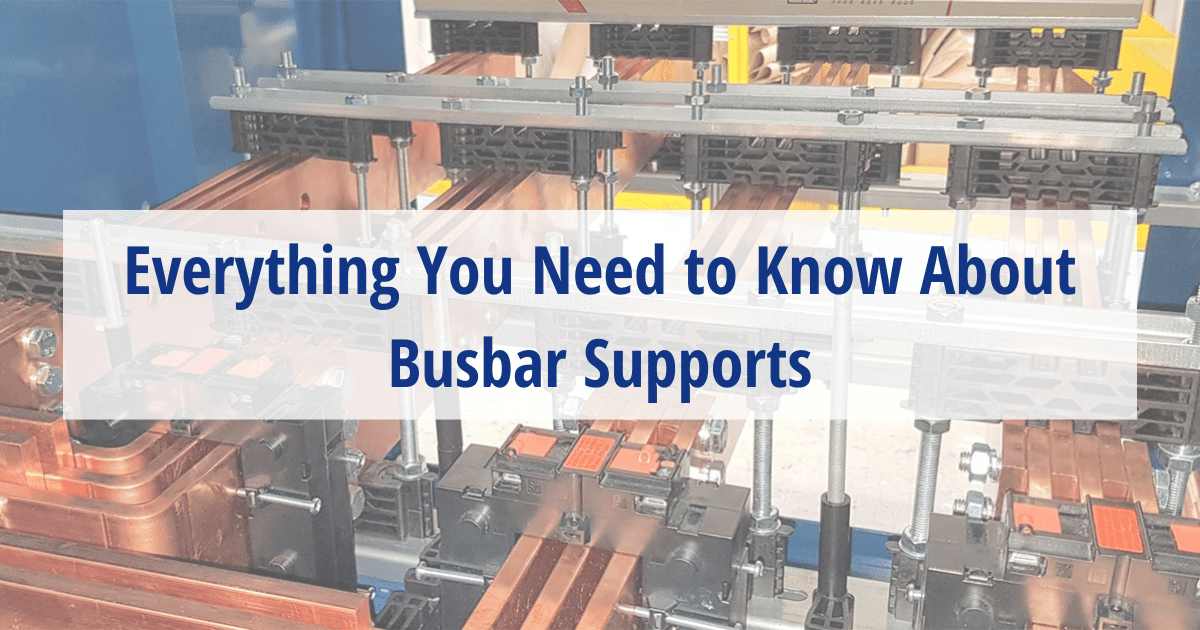
Busbar supports are designed to protect an assembly from the forces created by a short circuit fault, by holding the conductors in place. They’re made from electrical insulating material and come in a variety of sizes and shapes to accommodate different applications.
In addition to providing electrical insulation, busbar supports provide structural support to a busbar system. Sometimes busbar supports are referred to as clamps, because two supports, one on the top and one at the bottom, are used to sandwich the conductor into place. These types of supports are also referred to a comb supports.
A busbar clamp is the form of electrical connection to a busbar, where the conductor is not punched with a hole. The clamp creates pressure onto the main conductor and connecting cable lug or flexible conductor.
Due to peoples experience and they may use the terms busbar supports and busbar clamps interchangeably, but typically speaking, a busbar clamp is a piece of metal that clamps onto the busbar.
There is no defined size for busbar supports. Busbar supports are available in a broad range of sizes and shapes to suit different applications. Within Termate’s MX range, for example, there are thee lengths: 210 mm long. 273 mm long and 350 mm long.
The size of the support is often decided by the phase centre of the support. If you look at Termate’s busbar support ranges like the VMS (Versatile Mounting Support) each phase is a single VMS block rather than a multiple phase block and can be used at whatever phase centre a customer needs, but we also offer spacers that allow them to have a set phase centre to achieve higher fault ratings.
The size of the busbar support is also determined by the thickness of the conductor being held, the number of conductors per pole, and the orientation of the conductor (either flat or on edge). If you need assistance determining which busbar support would best meet your needs, speak to our technical sales team.
The weight that the busbar supports can hold is not determined by the material of the support. Much of the load bearing capability is determined by the method by which the busbar support is installed in the assembly.
Termate’s Busbar supports are used for a wide range of conductor sizes and a number of conductors per phase or pole. The focus is on making sure the supports have the appropriate short circuit current withstand rating.
When a conductors carries current, it heat up. The amount of heating will depend on the size of the conductor, its material and the amount of current passing through it. The busbar support holding the conductor must not be detrimentally affected by this heating.
The thermal limits are set out in the IEC 61439 series. These limits are based on the maximum temperature the conductor may reach. Therefore, to ensure that the busbar support is not a limiting factor to the performance of the assembly, Termate’s glass-reinforced polyamide busbar supports meet this requirement, the material for them being assigned thermal class F established using methods similar to IEC 60085.
Busbar supports installed in enclosures are not subjected to weathering extremes, however there is the need to ensure that the material the supports are manufactured from provides a insulation tracking resistance (CTI) suitable for its application. The environments are described in the standards as pollution degree.
This is very much dependent on the busbar support and the assembly it is installed in.
Design engineers use a variety of brackets, rails, channels and mountings to install busbar supports securely into an enclosure. For our standard MX range, you will need two supports per assembly. They are designed not to clamp down on the busbars but onto the support itself. Our MX supports on their own can hold 25 mm copper, but if larger busbars are needed we also offer spacers, allowing the larger busbars to fit without having to be clamped onto. The supports would then be secured to a mounting bar using M8 studs.
Please check for the particular installation requirements of your chosen support.
A busbar support can be made out of a material that has the suitable electrical insulation and mechanical strength properties. Some examples of these materials are glass reinforce polyamide which require a thermoplastic manufacturing processes.
Dough Moulded Compound (DMC), Sheet Moulded Compound (SMC) or Bulk Moulded Compounds (BMC). Can also be used, these materials are used in a thermoset manufacturing processes.
Through rigorous testing and expert technical understanding of the requirements of a busbar support, Termate manufactures busbar supports out a three different materials.
Our range of glass-reinforced black busbar supports are manufactured using injection moulded Glass Reinforced Polyamide 6.6.
Our range of beige DMC busbar supports are manufactured using Glass Reinforced Polyester.
Through our CNC service, we are also manufacturing busbar supports out of GPO3 polyester glass laminate.
For small distribution boards, we recommend the Termate DBBS (Distribution Board Busbar Support) range which is well-suited for this application.
These supports are suitable for 25 kA 3 s (at 315mm centers) or 50 kA 1 s (220 centers) and can hold 5 different sizes of copper bars, ranging from 20×5 mm to 30×10 mm.
For a large portion of the international markets, the appropriate standard is the IEC 61439 series, the standard for low-voltage switchgear and controlgear assemblies, within this standard series, there are performance characteristics and design verification requirements set out which low-voltage busbar supports will need to meet. For the North American markets, there are a number of applicable UL standards. UL1558 has some detailed requirements of the appropriate materials and also UL 891. Termate’s busbar supports have been tested and assessed to meet these standards. Please refer to the appropriate product page to access additional data.
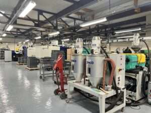
Termate manufacture Busbar supports. They are the only UK-based manufacturer of injection-moulded busbar supports. Termate has been in business for over 60 years and is based in Nottinghamshire, England.

To discuss any requirements you have for electrical insulating components, speak to our technical sales team.